-
Development of smart solar photovoltaic system having encapsulated phase change material with artificial intelligence based real-time condition monitoring
-
Induction heating via reversible disulfide bond grafted MXene for localized self-healing in thermoformable CFRP laminates
-
Community based Microencapsulated Phase Change Materials (MPCM) Assisted Hybrid Solar Agro-Processing Centers
The department was established in 1967 in the institute with the academic activities starting on 2nd November 1977. The Department is one of the oldest as well as finest in the zone and carries a rich legacy from thereon. From the very onset, the main objective of the department is to strengthen the academic and technical knowledge of the students through various world-class technologies, teaching-learning, and research activities. Over these glorious years of its journey, the department is keeping itself up to date with the latest technological and sustainable developments and trends in the field and with a dedicated faculty of highly qualified and experienced members in all streams of mechanical engineering. The curriculum is revised continuously with the active involvement of industry, alumni, research organizations, and other stakeholders, and UG and 03 numbers of PG programs are accredited by the National Board of Accreditation (NBA). The department offers 04 years B. Tech. in Mechanical Engineering, 02 years M. Tech. in Thermal Engineering, Design and Manufacturing, CAD CAM and Automation, Materials and Manufacturing Technology, and Renewable Energy and Ph.D. in different fields of Mechanical Engineering.
Our Vision
To develop high quality human and knowledge resources in the areas of Mechanical Engineering in order to cater to local, national, global economic and social demands.
The mission of the department is
- To train and transform young minds into responsible thinking engineers, technologists and scientists.
- To motivate them to attain professional excellence
- To inspire them to engage themselves for the betterment of the society with the use and applications of the latest tools and technology.
Our Mission
Important Notice
Academics & Program

Undergraduate
The B.Tech Programme consists of 8 semesters and is a professional engineering degree affiliated with and awarded after completion of 4-years of extensive/vast engineering study and research. Mechanical engineering students will learn about basic engineering techniques, like other engineering students, during the first-year course, which includes Engineering Mathematics, Physics, Chemistry, Electrical Engineering, Electronics Engineering, Engineering Mechanics, and basic Mechanical Activities (Welding, Fitting, Carpentry, etc.), Engineering drawing and Basic Programming. From the second year, they are exposed to core Mechanical Engineering subjects like Thermodynamics, Fluid Mechanics, Manufacturing Technology, Heat and Mass Transfer, Machine Design, Internal combustion Engine, Automobile Engineering, Instrumentation and Measurement are few to mention. This program is one of the most popular and demanded courses, not only in India but in the world.

Doctor of Philosophy (Ph.D)
The Ph.D. program is focused on original and innovative research that can lead to publications in premier journals and conferences. It is the highest level of degree that a student can achieve. Students are required to do some courses in the first few semesters (course work required can vary based on student background), but soon move on completely to research. Many Ph.D. scholars teach B.tech students also and many labs are run by them. After completing the program the scholar is capable of understanding significant advancements in Mechanical Engineering. The 1st Ph.D. graduated from the department was in the year 2010 and till date more than 125 research scholars received the Ph.D. degree from the department.

Postgraduate
The Department of Mechanical Engineering offers M.Tech programs in 5 contemporary and state-of-the-art specifications. The programs are designed such that a student can complete them based on advanced coursework and extensive laboratory sessions. The standard M. Tech. is a two-year program, where the first two semesters are spent doing courses. A one-year project commences at end of the 2nd semester. The project typically has a strong research component relevant to contemporary research and Industriels needs.
Faculty Advisors
Satyabrata Choudhury
ProfessorPhone: 9957182389
Email: scnitsilchar@gmail.com
Satyabrata Choudhury
ProfessorPhone: 9957182389
Email: scnitsilchar@gmail.com
Satyabrata Choudhury
ProfessorPhone: 9957182389
Email: scnitsilchar@gmail.com
Satyabrata Choudhury
ProfessorPhone: 9957182389
Email: scnitsilchar@gmail.com
Sponsored Projects

Faculty Members
Head of the Department
Over these glorious years of its journey, the department is keeping itself up to date with the latest technological and sustainable developments and trends in the field and with a dedicated faculty of highly qualified and experienced members in all streams of mechanical engineering. The curriculum is revised continuously with the active involvement of industry, alumni, research organizations, and other stakeholders, and UG and 03 numbers of PG programs are accredited by the National Board of Accreditation (NBA). The department offers 04 years B. Tech. in Mechanical Engineering, 02 years M. Tech. in Thermal Engineering, Design and Manufacturing, CAD CAM and Automation, Materials and Manufacturing Technology, and Renewable Energy and Ph.D. in different fields of Mechanical Engineering.
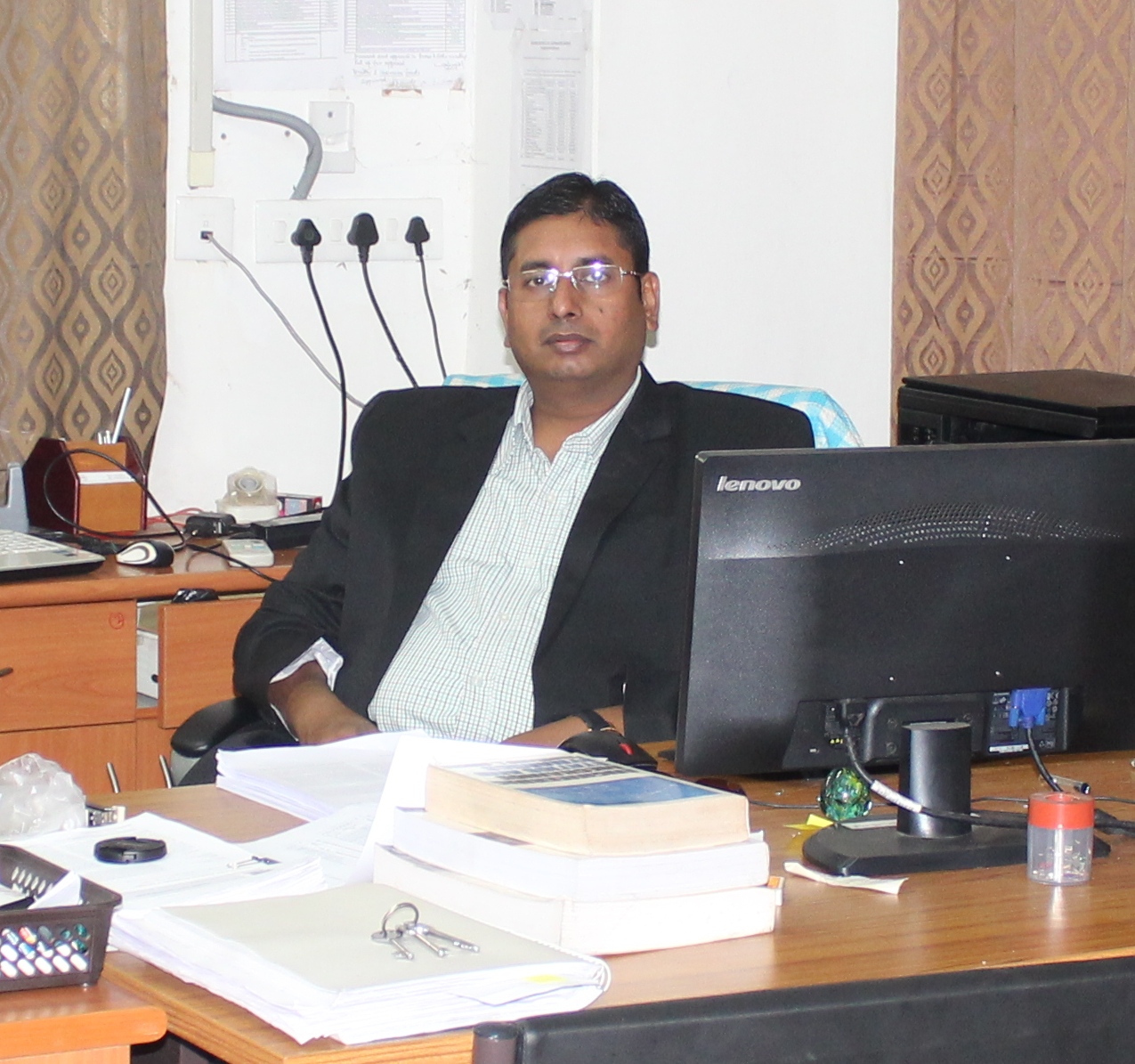
Dr. Sudipta HalderHoD, Department of Mechanical Engineering
Email: hod@mech.nits.ac.in

News and Updates


